Mechanical Design - Spectroscopy Chamber
This week the team explored mechanical designs for the spectroscopy chamber, which would hold the no-IR camera for spectroscopy, as well as the LEDs to help detect the microplastics within the water. Below is a CAD of the initial model.
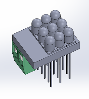
On the left side (square-shaped hole), the camera and the spectogram filter would be housed. On the right side, the LEDs would be housed. Below is a CAD of the LED array assembly proposed, on a potential PCB.
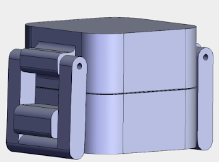
The slits towards the front of the spectroscopy housing were created to hold a potential garage door opener, which would allow water from a still body of water to flow into the chamber once opened, allowing for spectroscopy analysis. The goal was to add this chamber in a middle section of the Lilypod, with the filtration system below this structure, and a 'pad' above this chamber serving to close the entire product from the top.
Below is a rendering of the middle chamber:
The water would flow down from the spectroscopy chamber, with a trap door / valve blocking the flow to through the filtration mesh, until the spectroscopy analysis has been completed. The pH sensor would be held within this middle part, analyzing the water's quality. The electronics would be contained within the hollow volume divided from the water chamber, ensuring watertight seals and barriers.
Watch for our next blog posts for more developments on the mechanical design, as well as an introduction of the work on our software architecture!


Comments
Post a Comment