Mechanical Development - Middle Structure and Spectroscopy Enclosure
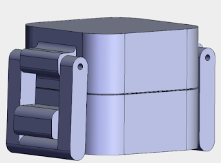
With the bottom section of the pod currently designed, the next step was to design the middle structure. With this being the main core of the system, it was decided that this volume would contain the majority of the electronics. The polluted water intake would occur within this structure, for sampling with the pH, conductivity sensors, as well as the spectroscopy. In addition, space for Arduino, Raspberry Pi, LiPo batteries, buck converters (for stepping down any voltages for peripheral components), servo motors for controlling the trap door (allowing water to fall to the bottom section for filtering) and the garage door (for unfiltered water intake) required allocation within the middle structure. These components needed to be separated from the water chamber, for obvious reasons. Finally, hexagonal imprints for the nuts of the locking mechanisms needed to be integrated at the top and bottom of the middle structure, such that a continuous fit between the bottom, middle and top modules could be achieved. Based on these design constraints and specifications, the following design was obtained:

As could be seen from the 3D view above, the spectroscopy region was allocated at the top of the middle structure. The rectangular area in the center would contain water, where the bulbs would be placed in a holder on one side, and the camera / prism would be placed in a small slit on the other side. A picture of the designed holder could be seen below:

An acrylic 'screen' could be placed in front of the spectroscopy tools (bulbs and camera), such that the water would not interfere with the electronics. Additionally, the indent at the top of the structure is for lining the connections with silicone for waterproofing from the exterior, when connecting the top module to the middle module. The same design was used for the connection between the middle module and the bottom module.
Exploring some of the internal designs within the middle structure, the following are a few sectioned views of the part.


In the first and second sectioned views, the cylindrical extrusion along the length of the flat surface of the pod would be used to house the pH sensor. The housing for the sensor was designed such that only the portion of the pH sensor required to test the water acidity (approx. the top 5 cm of the part) would protrude out into the unfiltered water section. Additionally, in the second figure, a pair of hole extrusions could be seen, with a rectangular imprint. This area would be used to hold the ultrasonic sensor, used to monitor the garbage level settled on the mesh filter in the bottom module. With the ultrasonic sensor registering a voltage value above / below a certain threshold, the system would automatically stop filtering until a manual reset is conducted, once the mesh filter is physically cleaned out.
Based on these designs, the next step would be to design the top module. This will be seen in a subsequent post.


Comments
Post a Comment