Posts

Showing posts from February, 2020

Software Development - Making Lilypod Intelligent – Part 3 (The Implementation)

Image
To implement the neural network, a Tensorflow backend with a Keras wrapper was used. The following is a visual representation of the network: It was designed to not be too deep since we do not have access to any pretrained layers that would be useful, nor do we have enough data to train the large number of parameters that a deeper network would have.  In addition to the model itself, an interface was built to allow hydroponic farmers to train the network with new data as well as to obtain a crop quality prediction when desired in an easy to use manner. To do this, a desktop app was built using Pygame and Matplotlib. The app displays a dashboard, showing graphs of the latest sensor readings of the water. Located beside the graph is an interface with two text fields and two buttons, each corresponding to a different text field. One text field allows farmers to input a crop score based on their own expertise. The button corresponding to that text field, when clicked, runs a

Software Development - Making Lilypod Intelligent – Part 2 (The Modification)

While we are unable to train and validate a working network due to lack of data, we are able to build a neural network architecture that is capable of learning the correlations between spectrometer data, pH levels, and conductivity measurements of the water to the quality of the resulting yield. After having created the neural network described in Part 1 of this blog, the learning capability of the network was validated by overfitting the network to dummy data. One dummy datapoint was created by running sensor measurements in a tub of salted water. An arbitrary percentage score label was then assigned to the measurement to indicate the hypothetical quality of the crops. Then, the network was trained on the single datapoint for a large number of epochs. What we found was that the LSTM neural network was unable to reliably overfit on the single datapoint. The loss value would decrease during training, but during inference time, the predicted score value would unexpectedly either jump

Software Development - Making Lilypod Intelligent – Part 1 (The Original Idea)

With our design, Lilypod now features three different water monitoring sensors: spectrometer, pH sensor, and conductivity sensor. These three sensors provide a wide array of data about the quality of the water which ultimately correspond to the quality of the yield (crops and fish). As such, these parameters would be beneficial for hydroponics farmers to closely monitor. While constant monitoring would provide farmers with a good level of utility, adding an aspect of machine intelligence would allow Lilypod modules to not only keep track of crucial data, but also predict the quality of the upcoming yield given a history of the water’s condition as well as provide farmers with suggestions on how to best optimize water conditions.   In order to build this feature, a machine learning model had to be designed. However, a significant problem faced was the inexistence of data relating spectroscopy data, pH data, and conductivity data to resulting crop quality. Without the data, the mode

Software and Electrical Development - Interfacing Progress

Image
Just wanted to update everyone on our current progress. As you can see below, we are hard at work in the integration of our sensors and actuators on-board our system. The development of our serial communication protocol is underway, and we are planning on testing the conductivity sensors soon (needed to obtain some nichrome and copper wires for this setup).

Mechanical Development - Middle Structure and Spectroscopy Enclosure

Image
With the bottom section of the pod currently designed, the next step was to design the middle structure. With this being the main core of the system, it was decided that this volume would contain the majority of the electronics. The polluted water intake would occur within this structure, for sampling with the pH, conductivity sensors, as well as the spectroscopy. In addition, space for Arduino, Raspberry Pi, LiPo batteries, buck converters (for stepping down any voltages for peripheral components), servo motors for controlling the trap door (allowing water to fall to the bottom section for filtering) and the garage door (for unfiltered water intake) required allocation within the middle structure. These components needed to be separated from the water chamber, for obvious reasons. Finally, hexagonal imprints for the nuts of the locking mechanisms needed to be integrated at the top and bottom of the middle structure, such that a continuous fit between the bottom, middle and top module

Software Design - Raspberry Pi Communication to the Cloud

This post outlines the three routine steps for RPi communication to the Firestore database. Sample State This routine step waits for the Arduino to inform the RPi about the latest state of all the sensors (contained within the data packet sent by the Arduino to the RPi). Information about the command package and the data package can be read in an earlier post. Check Garbage State This state checks the garbage level within the Lilypod, above the filtering mesh, with the use of the ultrasonic sensor. If the Arduino registers that the ultrasonic sensor is reading a value above a specified voltage threshold (to be determined based on testing), the system will completely shut down, and await a farmer to conduct a manual reset of the pod. Before the manual reset of the pod can occur, the filter must be cleared out.  Filter State One of the states is a filter state, where all the doors (trap and garage) are open, filtering water through without conducting any spectroscopy, pH sen

Mechanical Development - Bottom and Pump Housing

Image
Today, the team worked on the bottom section of our pod. Of focus in the bottom housing are the pump system for evacuating water out of the structure, as well as the filtration system with the fine mesh. Based on our electrical specifications, a boost converter was also required to step the voltage up for the pump, from the voltage output by the chosen LiPo batteries. Noting all the design requirements for the bottom section of the pod, a design was conceived in Solidworks, as shown in the following pictures. As seen through the second picture, the area with the four hexagonal imprints would house the pump and the boost converter. Essentially, the pump would be press-fitted between the two through-holes, connecting the filtered water container (see top section of second picture) to the external hole. In addition to the pump and boost converter, the mesh will be screwed into the extruded platform in the top section of the second picture. With approx. 10 cm of space between t

Software Design - Arduino <-> Raspberry Pi Interfacing - Arduino Communication Protocol

Image
Moving onto the Arduino communication protocol, the following data package is sent back to the Raspberry Pi, upon receiving a command package. To keep everything consistent, there are 10 floats sent between the Arduino and the RPi. Only 5 out of the 10 floats in the data packet are populated, after a certain actuation or reading is conducted. First, the state of the garage door (i.e. opening or closing) is recorded, as well as the state of the trap door. Three floats correspond to sensor readings, including the pH sensor value, the conductivity sensor value and the ultrasonic sensor voltage values (recommending whether the filter should be cleaned out). It is important to note that the RPi decides what routine step it is on, and then builds its command packet to be sent to the Arduino. Once the Arduino obtains this command packet, and conducts the required polling and actuations, the data packet is sent back to the RPi. The RPi then logs any important data on the Firestore datab

Software Design - Arduino <-> Raspberry Pi Interfacing - RPi Communication Protocol

Image
This blog post focuses on the interactions between the Arduino and the Raspberry Pi. More specifically, the serial communication protocol being used between the two modules. Check out the post on the Overview of Architecture to refresh your memory on the components connected to each of the modules. Starting with the Raspberry Pi, this is our command hub. All commands are sent from the RPi, based on the current state of the robot. This could essentially be considered as the 'brains' of our pod. A command packet is sent from the RPi to the Arduino, consisting of 10 floats, with a start and end byte to locate the start and end of the message. The RPi command packet can be seen in the following figure. Briefly walking through each of the commands in the packet, the intended state of the pump is the first float sent in the package (i.e. whether the pump should be pumping water out of the chamber (ON) or not (OFF)). Next, the bulb state is sent, turning the bulbs ON or OFF

Mechanical Development - Finalized Locking Mechanism

Image
Based on the results of our tests with the locking mechanism (see Watertight Locking Mechanism post), we decided to finalize on a lock design, as seen in the picture below. The lock is pretty much the same as the one seen in the post, suggesting that our waterproofing tests went well. Along with silicone for sealing any potential air gaps, it is possible to ensure that the three sections of our pod will be tightly fitted together. c-Clamps would be used to connect the locks, through the thru-holes between the two sections. The locks would be positioned on the hexagonal imprints located at strategic points on the circumference of the entire Lilypod structure. Check for a full assembly of the pod, in a future post, to visualize the physical interactions between each section of the bot.

Software Design - Rough Software Loop

Image
Focusing on the software design, the team came up with a rough look at the software loop. The components of the software loop will be referred to in upcoming software blog posts.

Software Design - Overview of Architecture

Image
This blog post will speak more about the software architecture within the Lilypod system. Giving an overview of the architecture, there are three main modules within the system: a Raspberry Pi, an Arduino and the Client, for running all operations. A flow chart will be presented in a following blog, connecting all the sensors and actuators in the system to their corresponding modules. However, this post covers the underlying use cases of each of the modules. RASPBERRY PI Firstly, the Raspberry Pi 4 , is responsible for routine management within the system. It helps decide the next steps for the overall robot, based on the current status. For example, if the pod is ready for a new treatment cycle, then the RPi will check all necessary actuators and sensors to ensure the entire robot is ready to intake polluted water for cleaning. Additionally, the spectroscopy and image processing is conducted through the RPi. As seen in the picture below, the no-IR camera is connected directly t

Mechanical Design - Watertight Locking Mechanism

Image
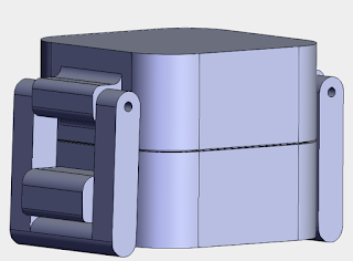
To solve the issue of protecting the electronics from water damage from the external water body, several locking mechanisms were explored, connecting the middle interface (i.e. spectroscopy chamber and internal water flow), the bottom interface (pump and mesh) and the top interface (pad and flotation devices). This was explored in a manner which would ensure no water would flow between the connecting parts. Below is a rendering of the chosen locking mechanism: The above part was meant to serve as a prototype, where a latch from the above part would lock under a solid extrusion in the bottom part, similar to a tupperware container. Based on this prototype, the locking mechanism would be placed at three calculated points around the circumference of the entire Lilypod, for each interface between connecting parts (i.e. three for each interface). This prototype was sent for 3D printing to be tested. Check back on the outcome of this test!

Mechanical Design - Bottom Pump Interface

Image
The next step after designing the spectroscopy and filtering chambers was to conceive a design for the pump interface, which would extract the filtered water from the contraption and send it back into the water body. Below is a rendering of this design: The mesh filter would be secured with screws on the offset extrusion, mid-plane within the lower compartment (as seen in the drawing). Water would then fill up the bottom of this compartment, and a pump (located in the top compartment), would pump the water out towards the open water body (depicted by the hole on the outer round shell). This piece would be connected under the entire contraption, allowing for seamless water flow from the spectroscopy chamber and back into the water body. With the filter being placed on the inner offset extrusion, the microplastics would pile up on top of this filter. Once the filter is unable to hold any more microplastics, this bottom housing could simply be removed to clean the filter for re-use w